Link modules
5 kW to 1 MW family at a 1.0 m air gap.
NWPT modules
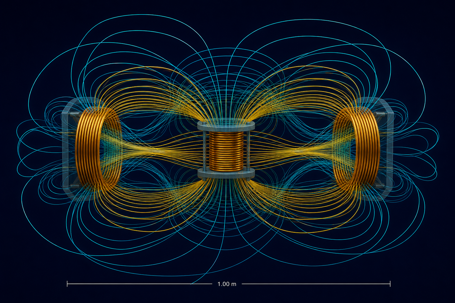
Three configurations, shared architecture. Every figure in the table is simulated.
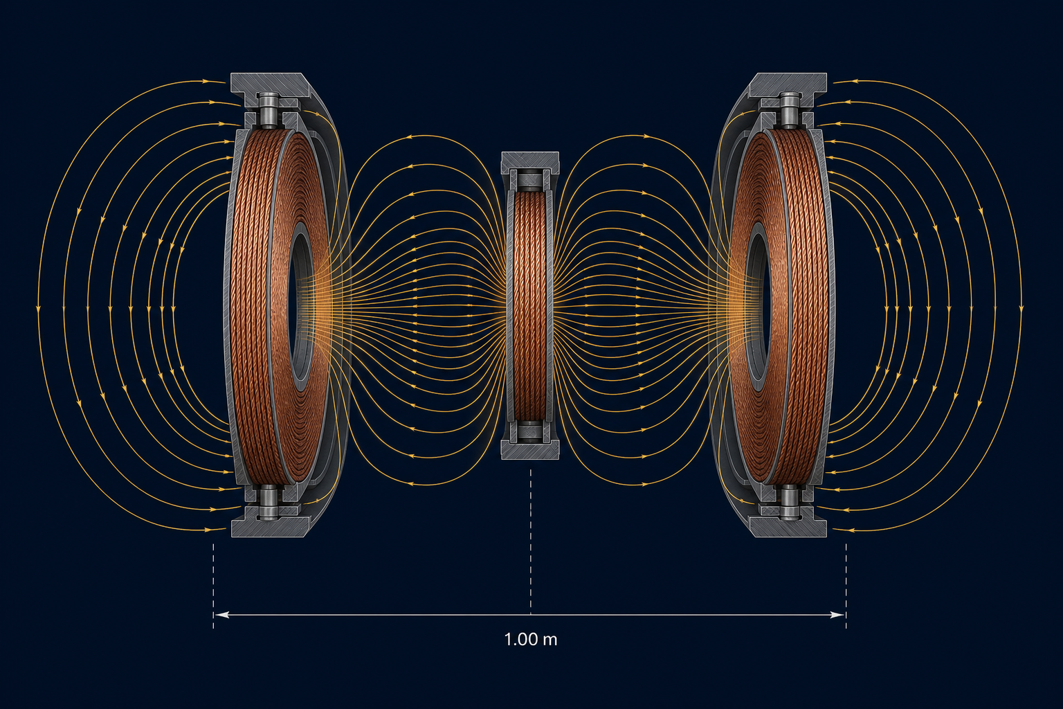
From one module to a 1 MW site
The 5 kW research link is the physics article. The next step is a 25 kW module with a kV-class tank and partial-discharge qualification (G2).
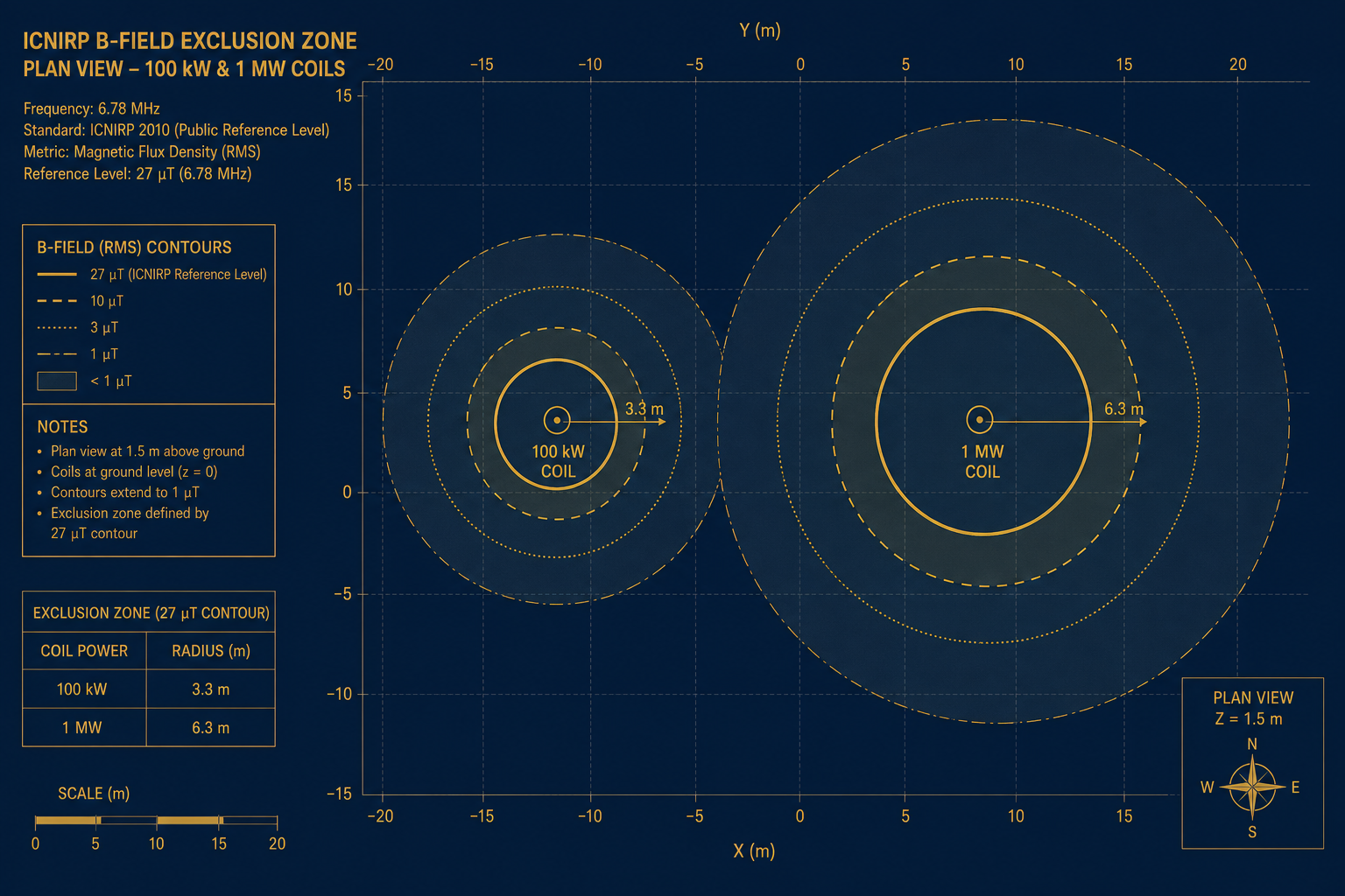
100 kW is 4 × 25 kW with current sharing (simulated: k = 0.156 / 0.062, η = 98.42 %). 1 MW is 2 × 500 kW at 10 kHz, 3.50 m pancake, k = 0.256, η = 98.84 % (simulated), about 240 kg of copper and a 1.12 MVA MV connection.
| Research link | 100 kW system | 1 MW system | |
|---|---|---|---|
| Status | specified | studied | studied |
| Architecture | three-coil relay | 4 × 25 kWsim. | 2 × 500 kWsim. |
| Gap | 1.0 msim. | 1.0 msim. | 1.0 msim. |
| Frequency | 85 kHzsim. | 85 kHzsim. | 10 kHzsim. |
| Coil | 1.10 m dia, axial stacksim. | 1.70 m diasim. | 3.50 m dia pancakesim. |
| Coupling | 0.117 relay / 0.037 directsim. | 0.156 / 0.062sim. | 0.256sim. |
| Coil-to-coil η | 97.18 %sim. | 98.42 %sim. | 98.84 %sim. |
| Controlled-zone radius | — | 3.3 msim. | 6.3 msim. |
The 1 MW configuration needs roughly 240 kg of copper conductor and a 1.12 MVA medium-voltage connection — concrete numbers an industrial reader can sanity-check.
| Solver | Physics | f | Unknown | Mesh | Acceptance |
|---|---|---|---|---|---|
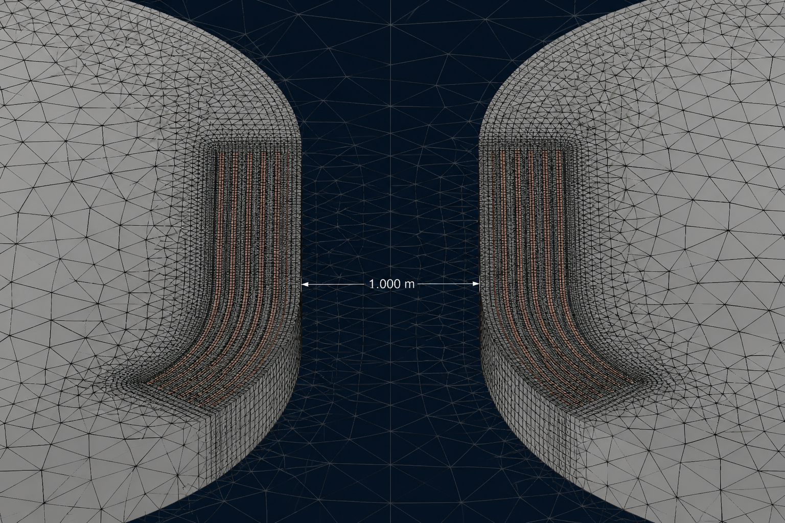
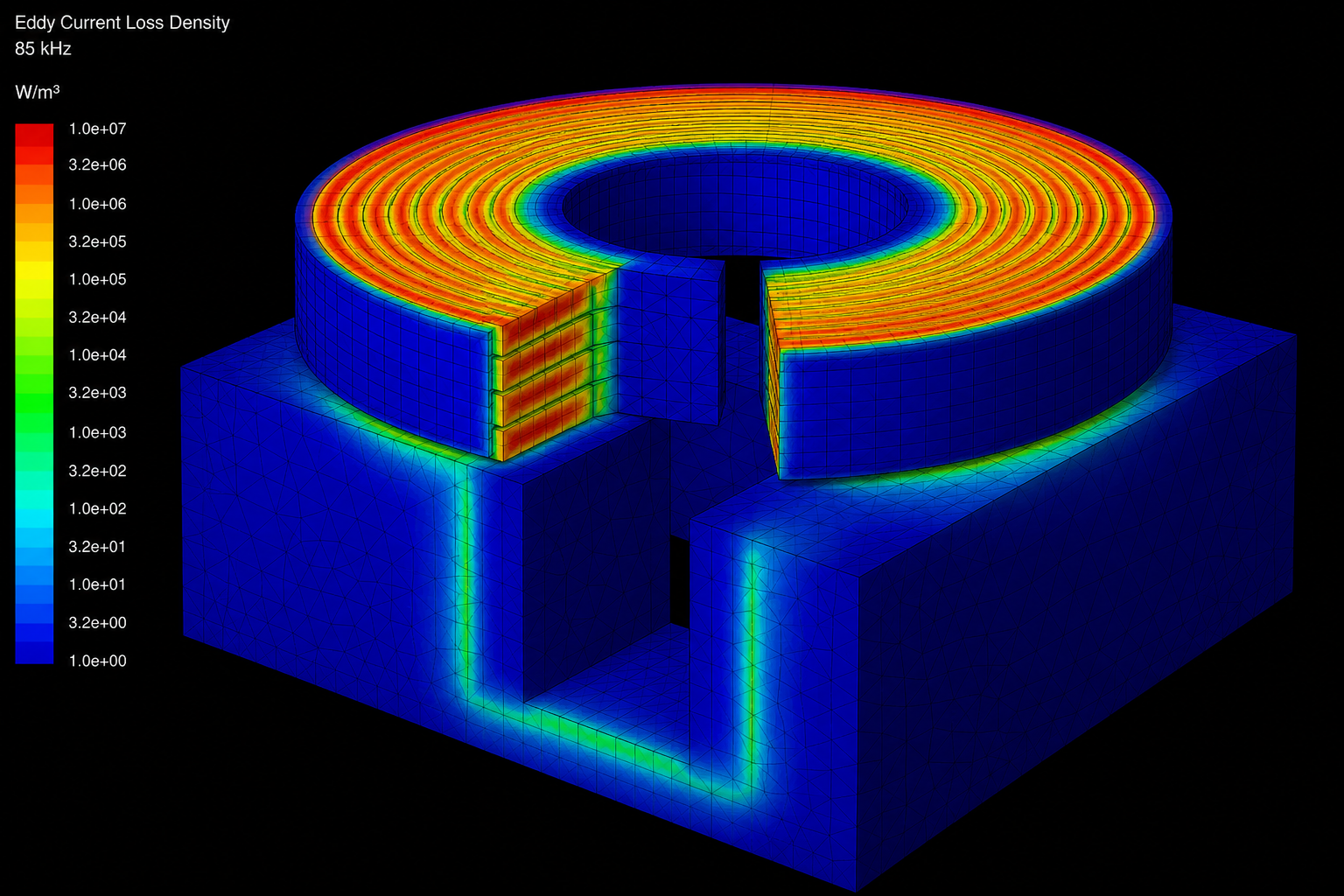
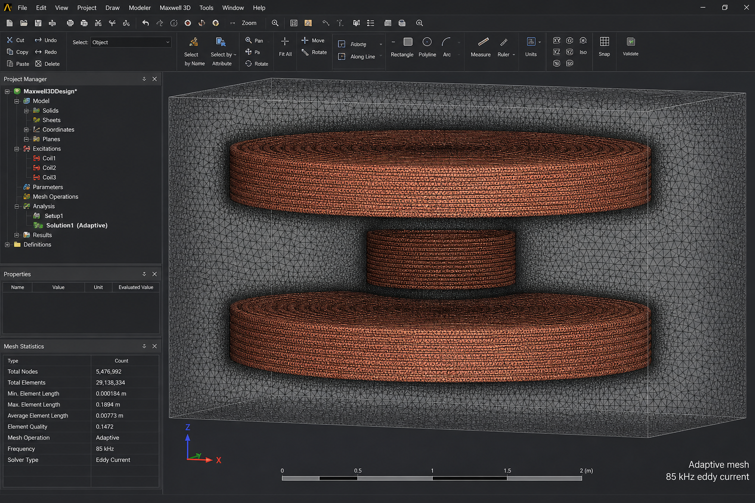
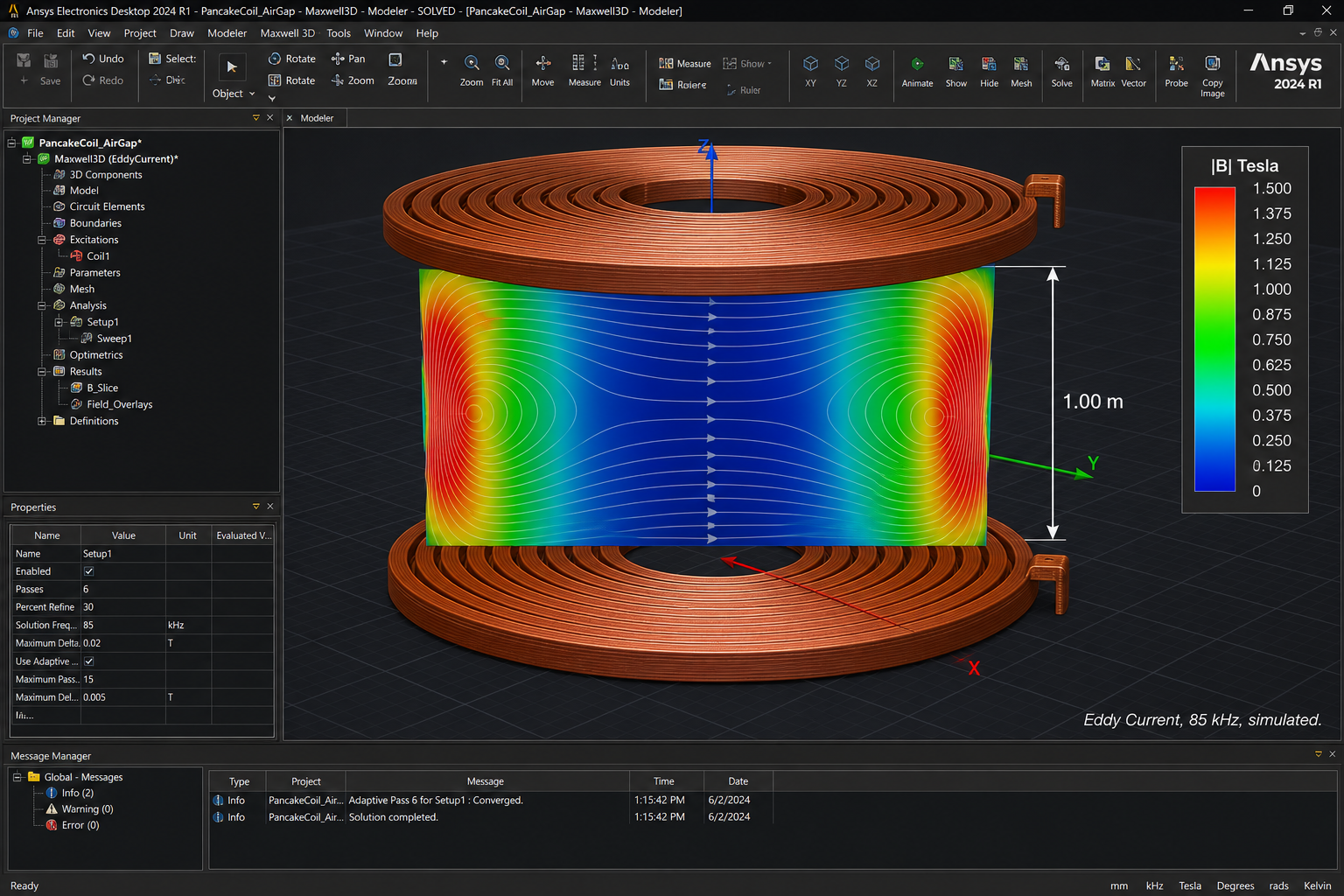
| Ansys Maxwell 3D | Eddy Current | 85 kHz | A | tetra + prism | M, k, R_ac, P_eddy |
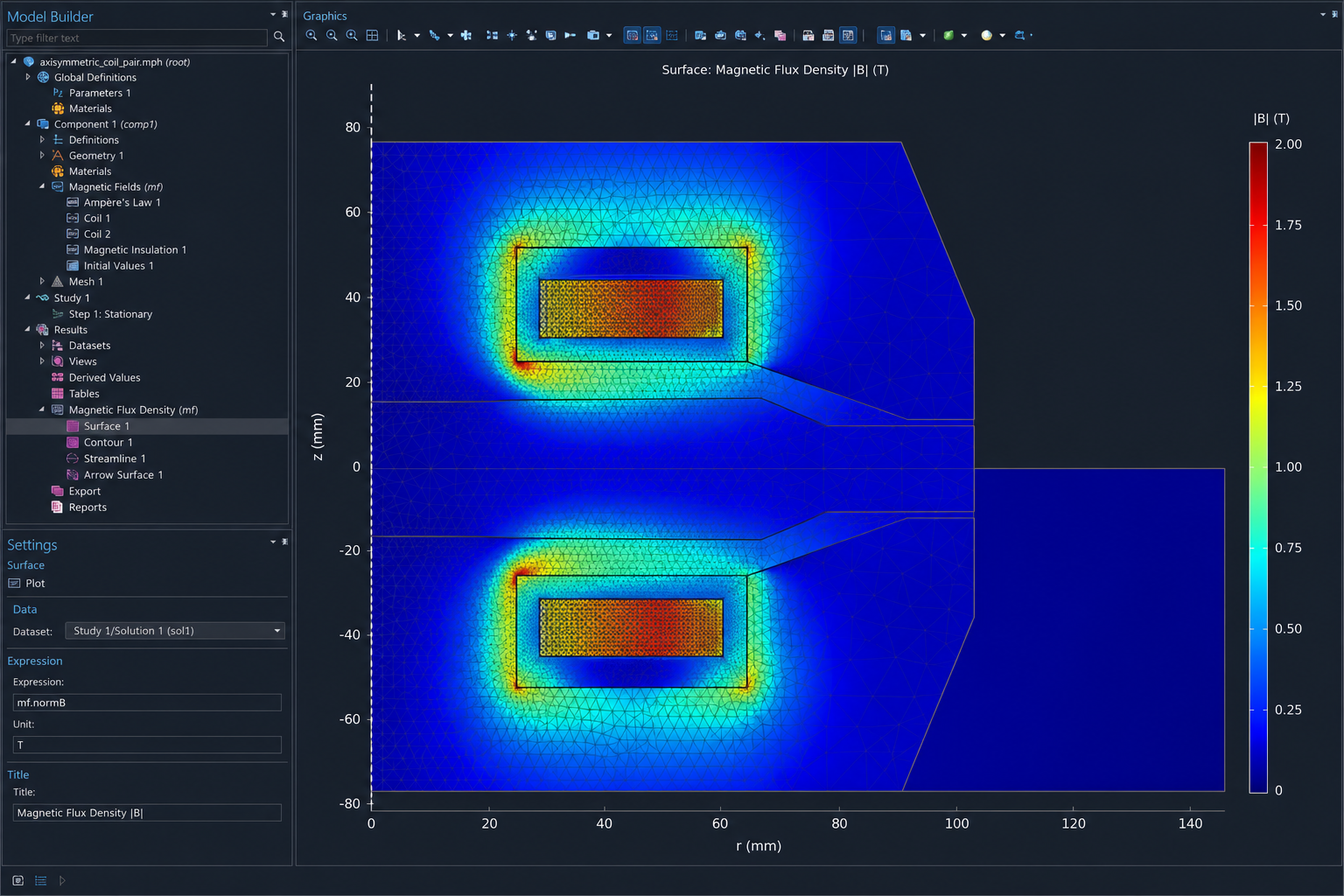
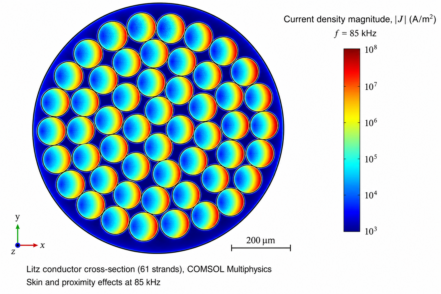
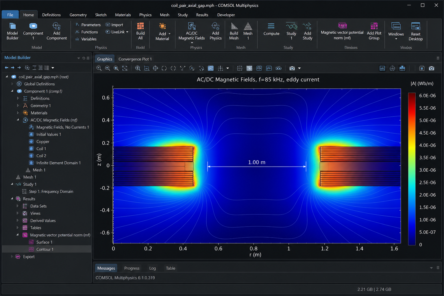
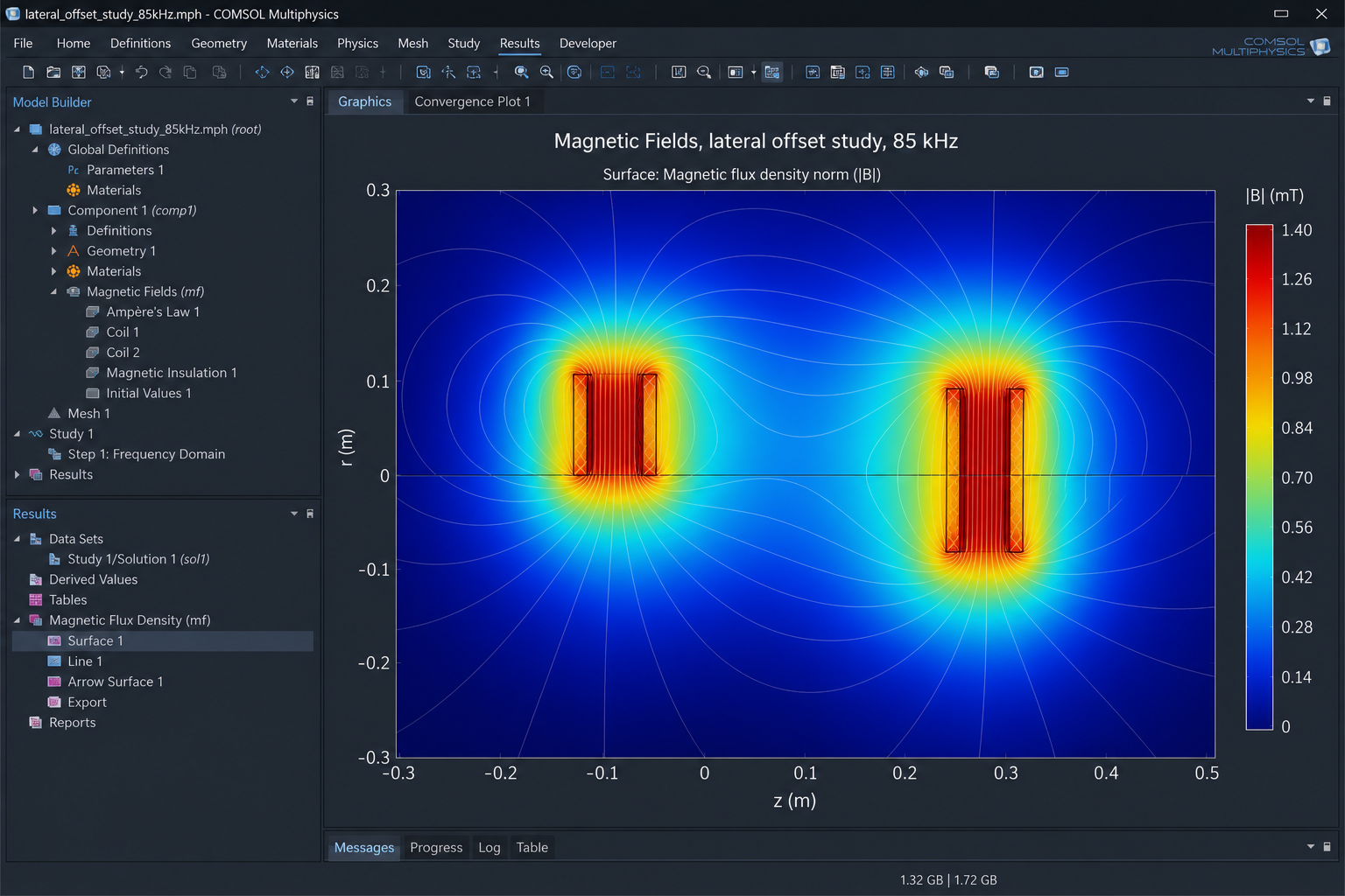
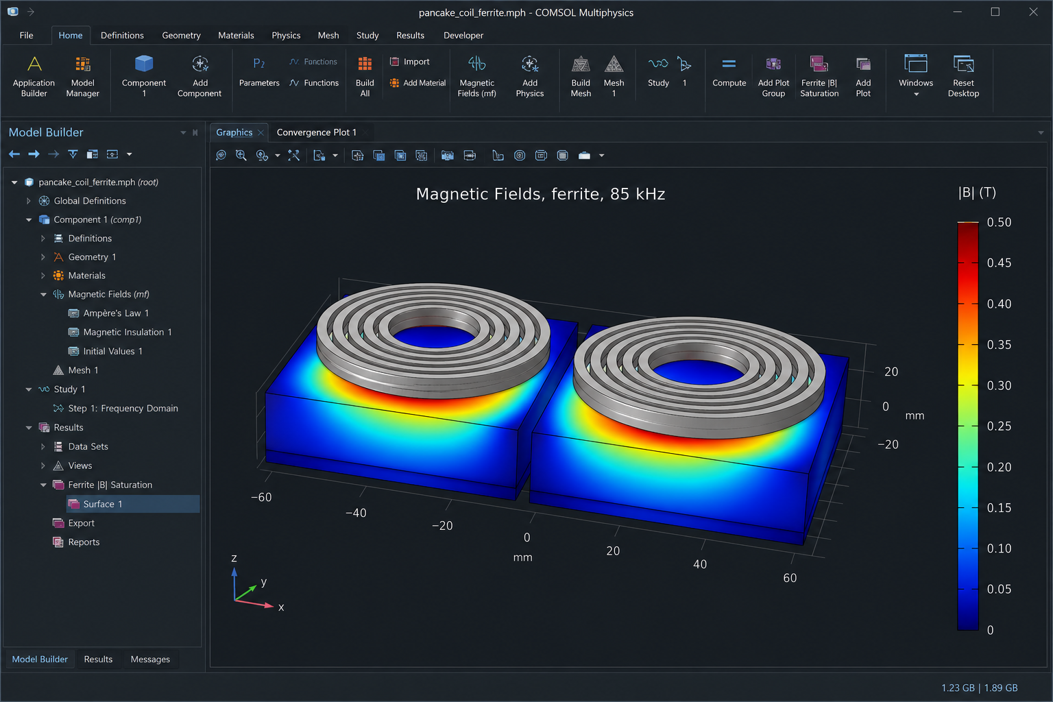
| COMSOL AC/DC | Magnetic Fields | 85 kHz | A_φ (2D-axi) | mapped + refine | J_Litz, |B|, ferrite |
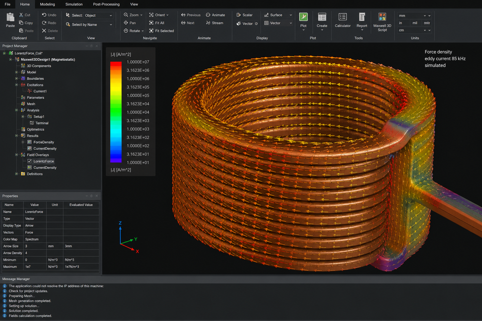
| COMSOL 3D | Magnetic Fields | 85 kHz | A | adaptive tetra | k(Δx), F_Lorentz |