Technology
Resonant inductive coupling, three-coil relay, Litz, frequency and ICNIRP zones.
Almost all commercial wireless power transfer works across 10–20 cm. A metre is not the same problem with larger numbers: the figure of merit and the reactive power change regime.
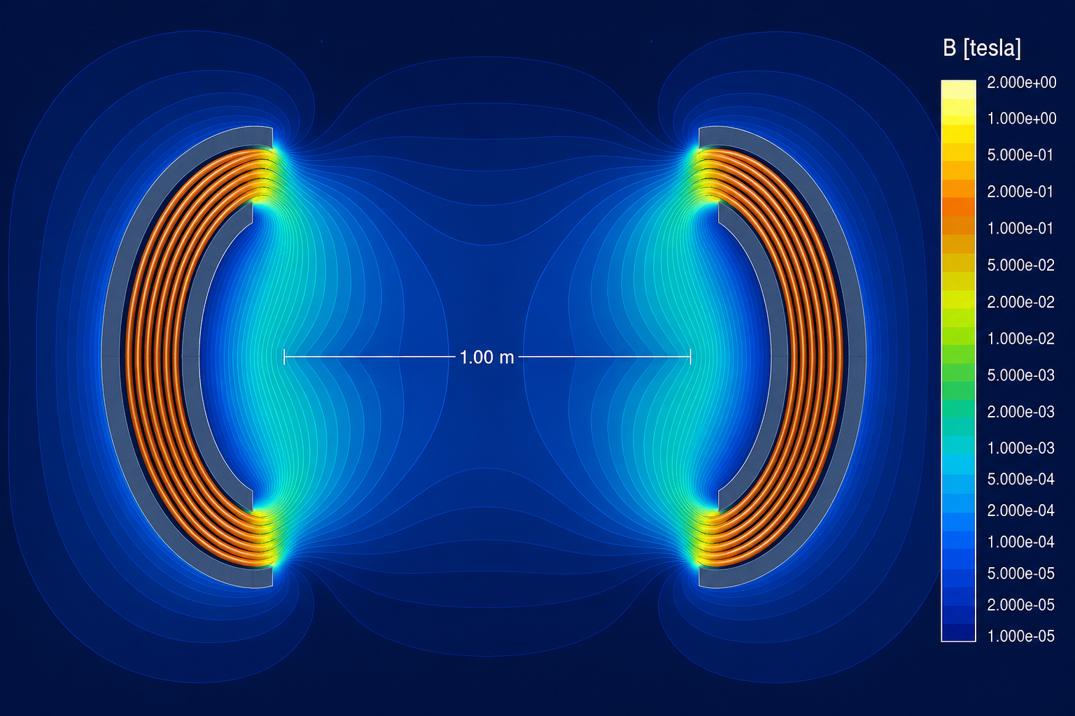
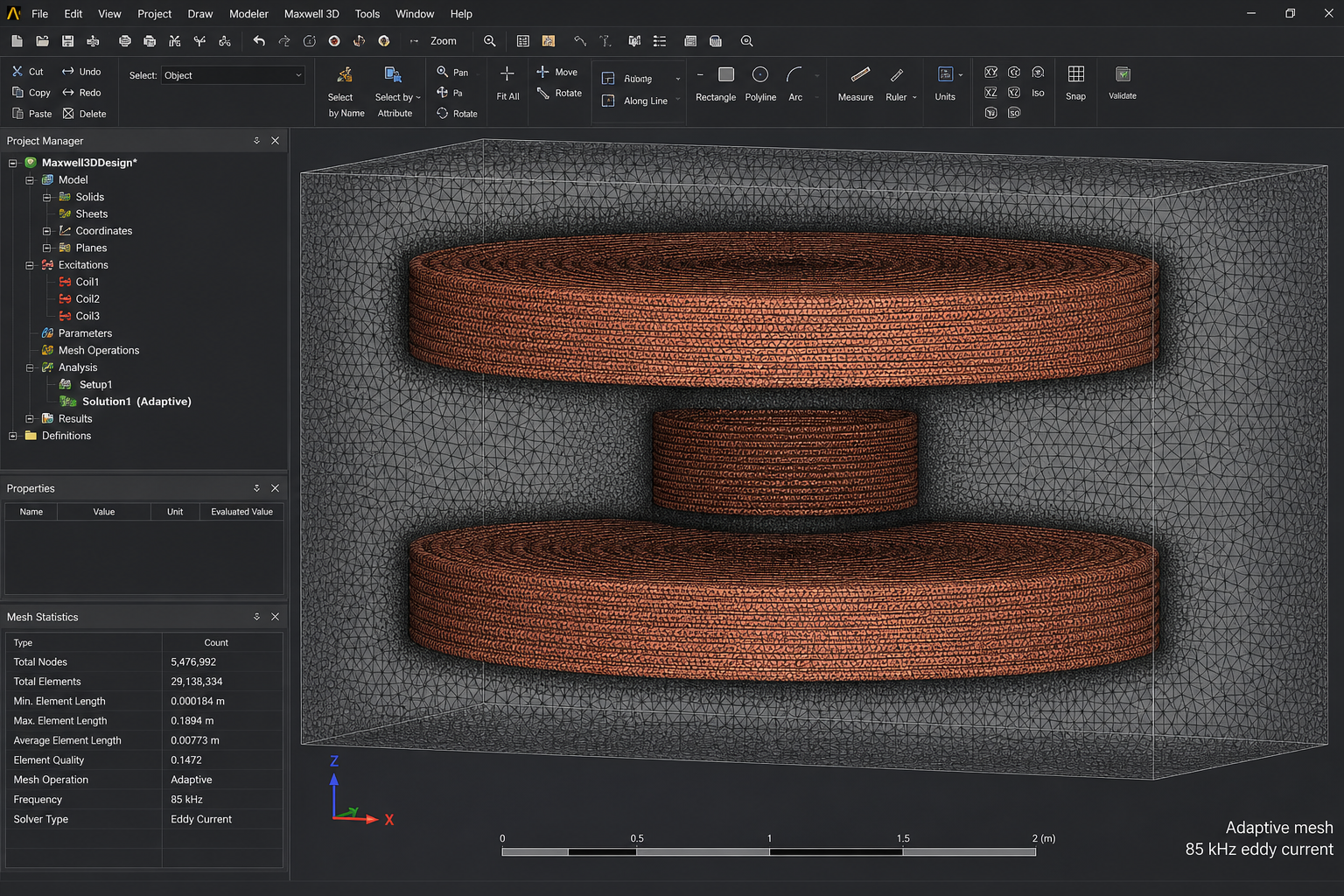
Maxwell 3D model of the 5 kW link
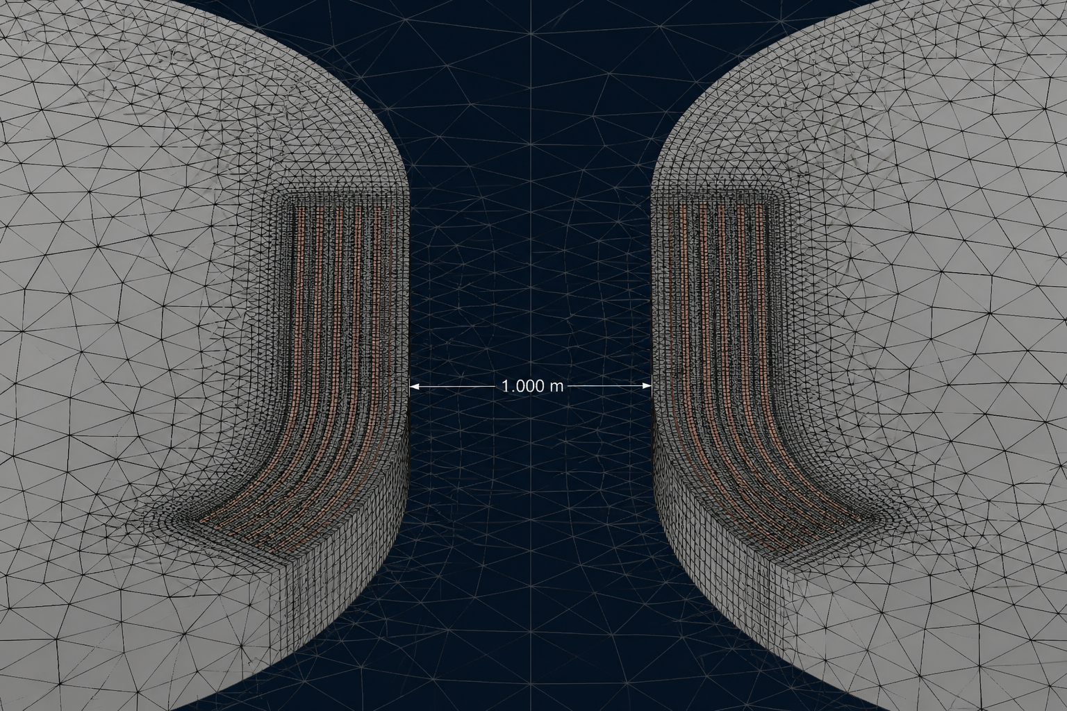
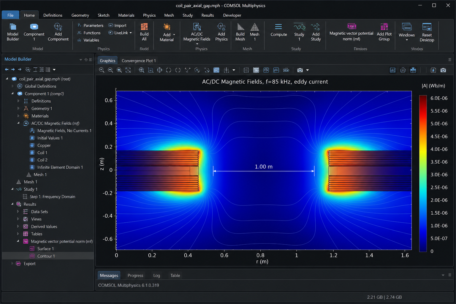
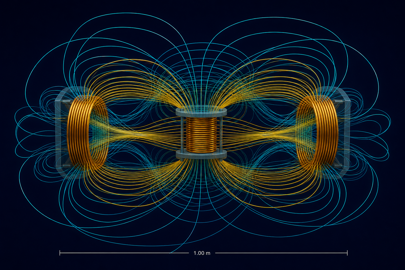
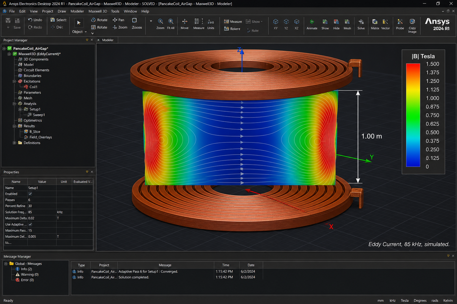
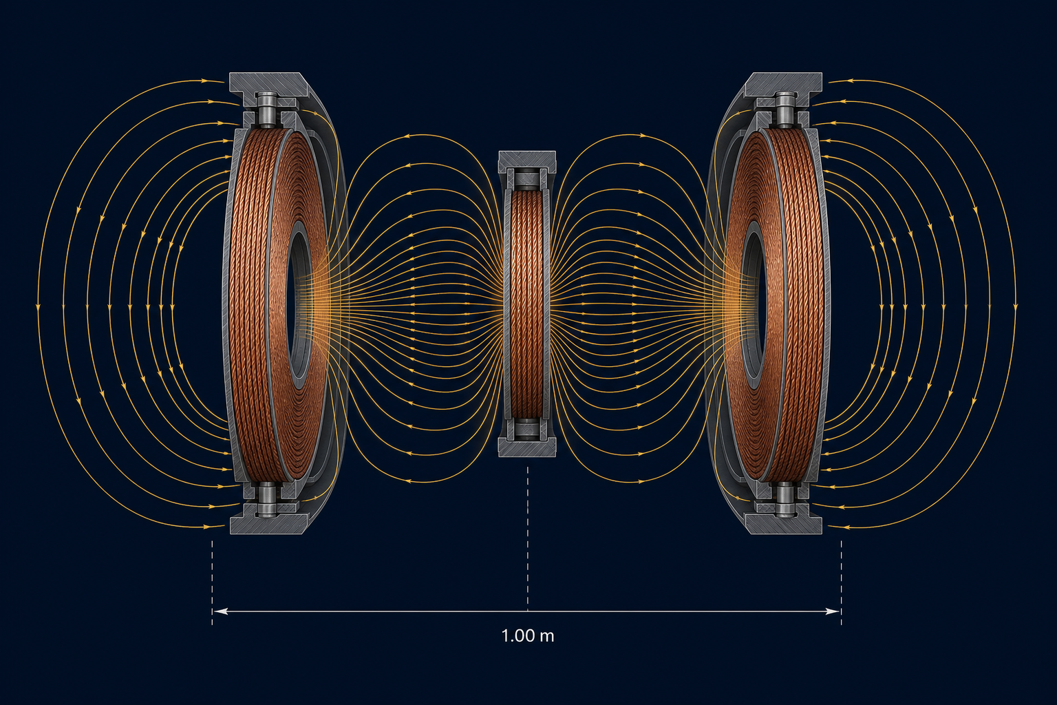
The coil set (1.10 m diameter, axial stack, three-coil relay) was solved in Ansys Maxwell 3D at 85 kHz. Coupling is k = 0.117 on the relay path and k = 0.037 direct (simulated).
Coil-to-coil efficiency at the optimal load is 97.18 % (simulated). The system has not been energised above 1 kW. Gate G0 measures L, M and R_ac of the physical set.
S_tank / P_out ≈ 1/k. At k ≈ 0.12 the tank must handle about eight times the active power.
Q, Litz and loss
97 % efficiency needs U ≥ 65.7. With k = 0.117 that requires √(Q1 Q2) ≥ 560, so Q of order 600–1200 after the conductor upgrade (G1).
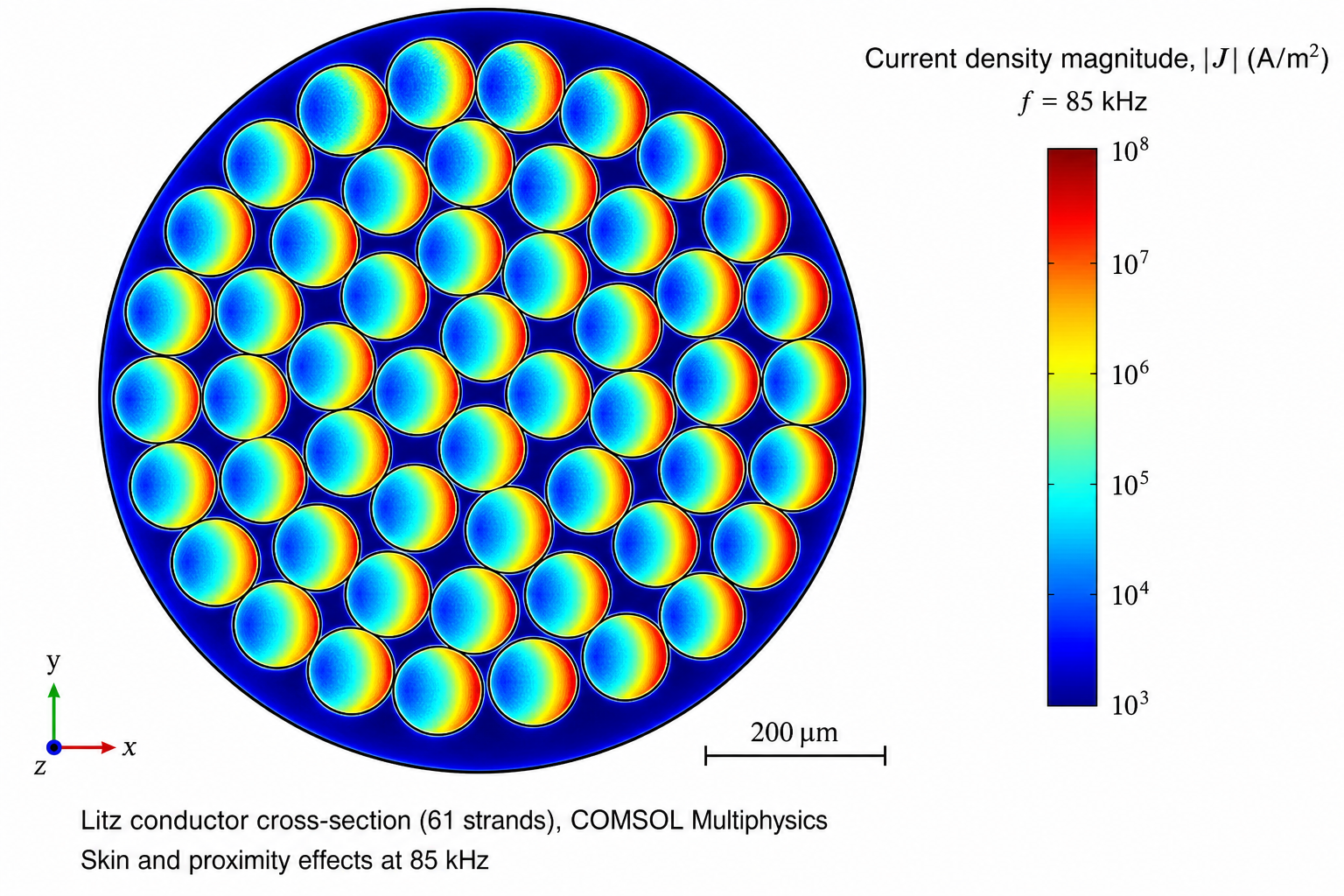
In Litz at fixed packing the proximity factor scales as n · d_s^4. The manufacturing package sets strand diameter and count to hold R_ac at 85 kHz without excess copper.
FEM method — Ansys Maxwell 3D and COMSOL
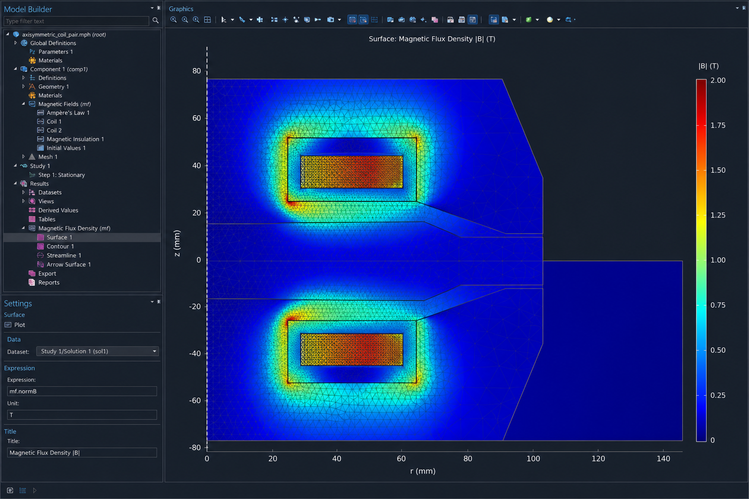
The magnetic domain is solved in Ansys Maxwell 3D (eddy-current, 85 kHz) and cross-checked in COMSOL AC/DC Magnetic Fields for mesh quality and Litz current density. Boundary: A × n = 0 on a surface at least five coil radii away; axial symmetry where a 2D-axi model is valid.
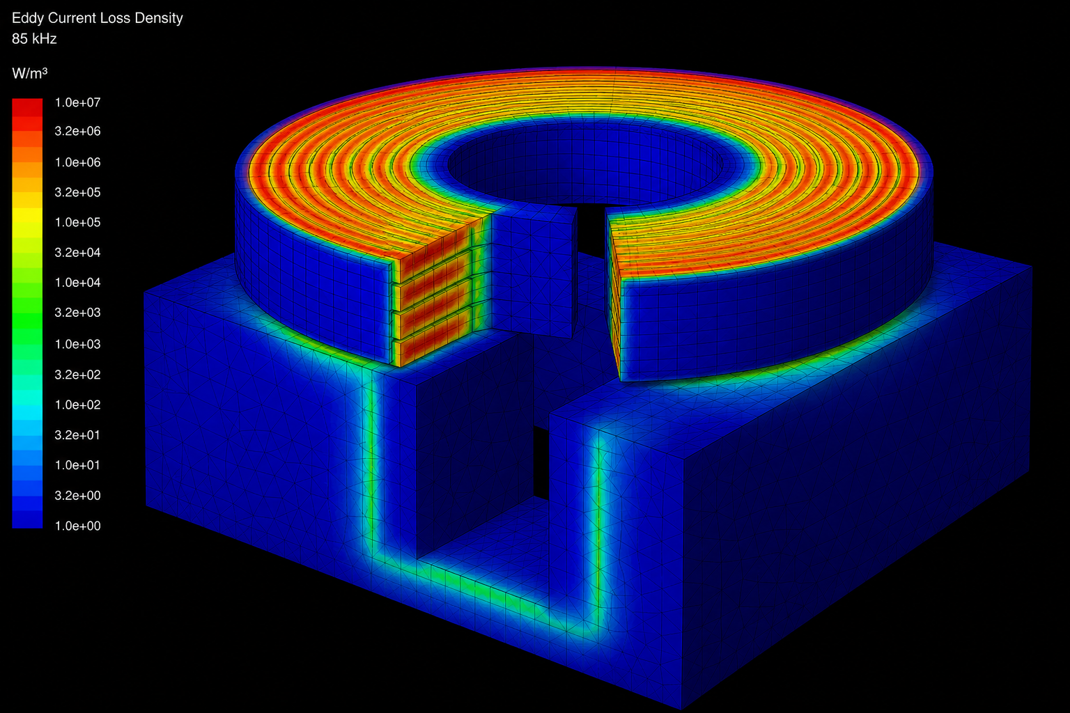
Mesh: tetrahedra in air, prisms in the copper turns, refined to δ/3 of the 85 kHz skin depth. Convergence: M and R_ac change by less than 0.5 % between adaptive passes.
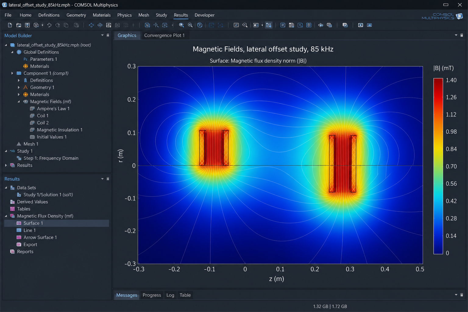
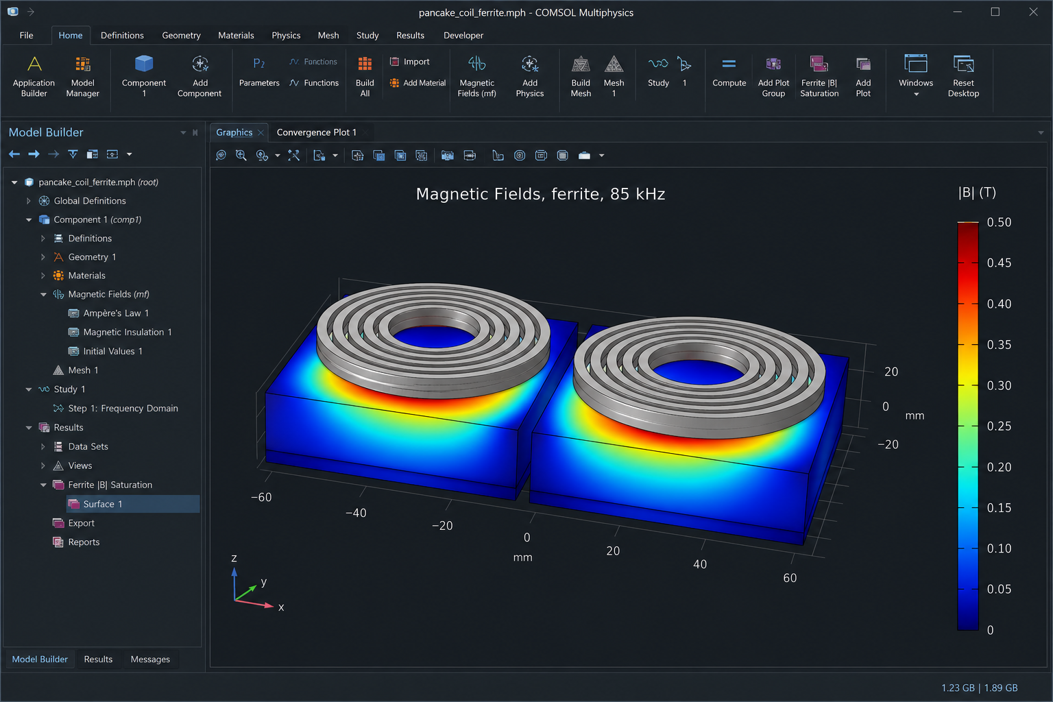
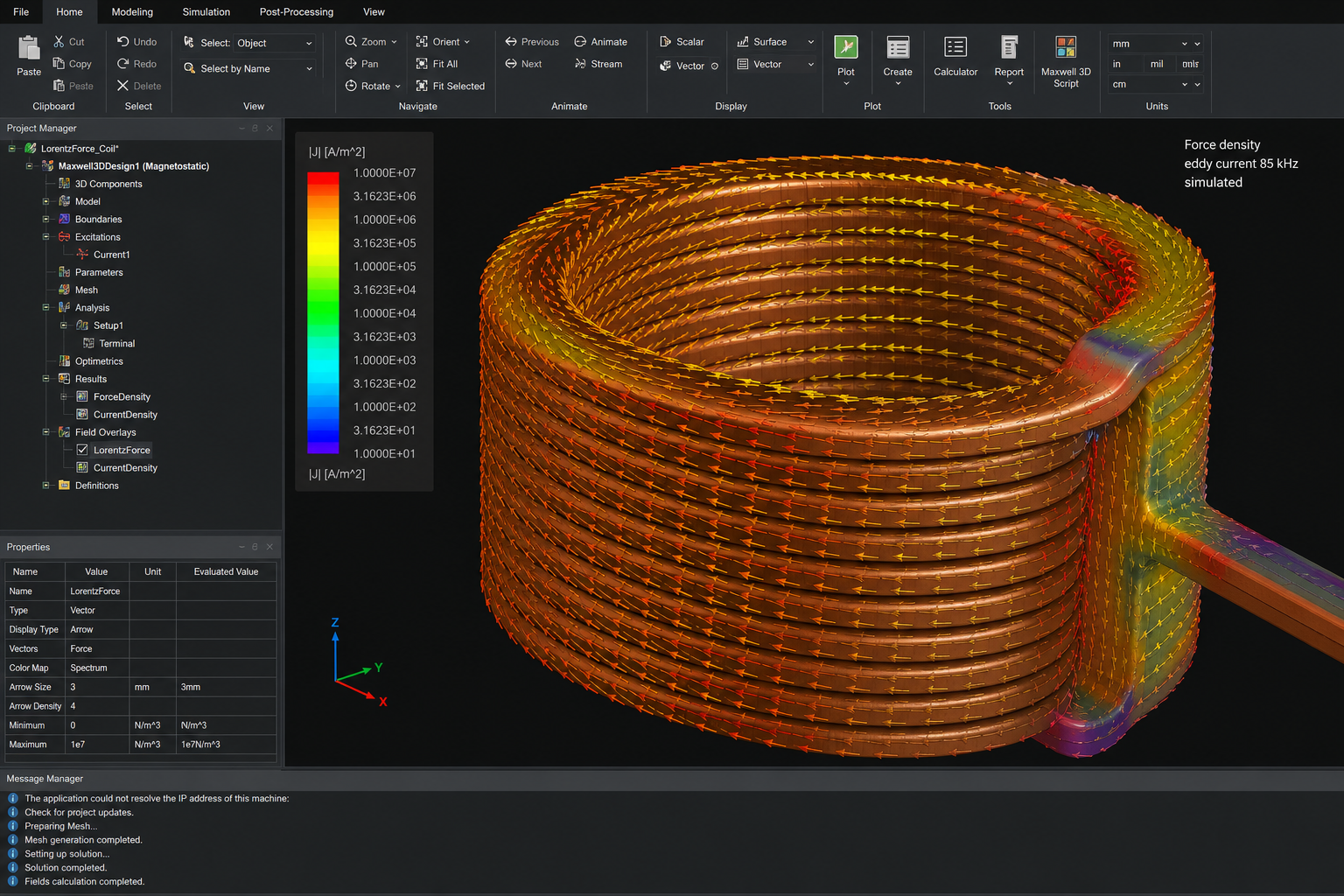
Post-processing: |B|, A_φ, flux lines, eddy loss P = ∫ (J·E)/2 dV, Lorentz force density, and k = M/√(L1 L2). Parametric studies: gap, lateral offset and ferrite saturation. Every number on this page is simulated until G0 measures L, M and R_ac.
Resonant coupling and U
The two-coil link is described by the figure of merit U = k√(Q₁Q₂). Link efficiency at the optimal load is η = U² / (1 + √(1+U²))².
80 % needs U ≈ 8.9; 90 % needs 19.0; 95 % needs 39.0; 97 % needs 65.7. At a metre, k is small; Q has to pay.
Three-coil relay
A passive intermediate coil raises effective coupling and lowers transmit-side tank voltage.
It does not reduce total circulating reactive power — it relocates it into the passive relay tank. That is the sentence a specialist reader needs to see.
Litz conductor
At fixed packing the proximity factor scales as n·d_s⁴. Finer strands buy more than more copper. The 5 kW manufacturing package starts from that result.
Frequency
85 kHz is an automotive standard, not a physical optimum. Megawatt-scale industrial links belong nearer 10 kHz, where conductors, capacitors and semiconductors are mature commodities.
EMF, ICNIRP, controlled zone
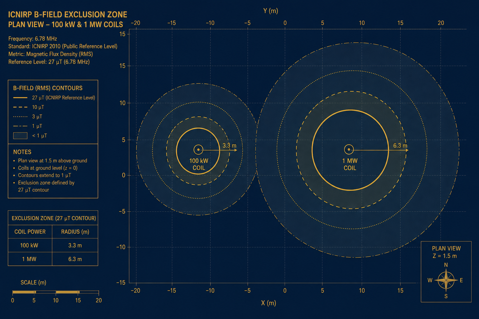
A 1 m high-power link needs a controlled zone of several metres radius. This is not a footnote: it shapes the installation concept.
Mining and ports already operate fenced sites. For those buyers the zone is a design input, not a hidden obstacle.
Eddy-current formulation and the Neumann integral
In the frequency domain Maxwell eddy-current solves ∇ × H = J + jωD with J = σE in copper. Mutual M is the Neumann integral; FEM extracts it from W = ½ Iᵀ L I and sets k = M/√(L₁L₂).
Model acceptance is not how the field looks: it is the stability of M and R_ac (< 0.5 %) between mesh adaptations, cross-checked in Maxwell 3D and COMSOL.
Misalignment and saturation
A lateral offset Δx breaks axisymmetry: the study becomes 3D. k(Δx) falls; the three-coil relay softens the drop relative to the direct path.
Ferrite backing concentrates flux and raises k, but local |B| can approach saturation. That map is post-processed in COMSOL; Lorentz force on copper is extracted in Maxwell.
| η | U |
|---|---|
| 80 % | 8.9 |
| 90 % | 19.0 |
| 95 % | 39.0 |
| 97 % | 65.7 |
Ansys Maxwell 3D and COMSOL post-processing
| Solver | Physics | f | Unknown | Mesh | Acceptance |
|---|---|---|---|---|---|
| Ansys Maxwell 3D | Eddy Current | 85 kHz | A | tetra + prism | M, k, R_ac, P_eddy |
| COMSOL AC/DC | Magnetic Fields | 85 kHz | A_φ (2D-axi) | mapped + refine | J_Litz, |B|, ferrite |
| COMSOL 3D | Magnetic Fields | 85 kHz | A | adaptive tetra | k(Δx), F_Lorentz |